- 4.1 3.5 Packet Tracer Configuring Ipv4 And Ipv6 Interfaces Setup
- 4.1 3.5 Packet Tracer Configuring Ipv4 And Ipv6 Interfaces Configuration
- 4.1 3.5 Packet Tracer Configuring Ipv4 And Ipv6 Interfaces Dhcp
- 1.1.3.5 Packet Tracer - Configuring Ipv4 And Ipv6 Interfaces

- 1.1.3.5 Packet Tracer – Configuring IPv4 and IPv6 Interfaces: 1.1.4.5 Packet Tracer – Configuring and Verifying a Small Network: 1.3.2.5 Packet Tracer – Investigating Directly Connected Routes: 2.2.2.4 Packet Tracer – Configuring IPv4 Static and Default Routes: 2.2.4.4 Packet Tracer – Configuring IPv6 Static and Default Routes.
- View Lab Report - 4.1.3.5 Packet Tracer - Configuring IPv4 and IPv6 Interfaces Instructions from MSIS 647 at Touro College. Packet Tracer - Configuring IPv4 and IPv6 Interfaces Topology Addressing.
Step 2: Configure the two customer LAN switches. Configure the IP addresses on interface VLAN 1 on the two customer LAN switches. Make sure to configure the correct default gateway on each switch. Step 3: Configure the PC interfaces. Configure the IP address, subnet mask, and default gateway settings on PC-Aand PC-B.
Packet Tracer - Configuring IPv4 and IPv6Interfaces
Please click here to download topology4.1.3.5 Packet Tracer - Configuring IPv4 and IPv6 Interfaces Instructions
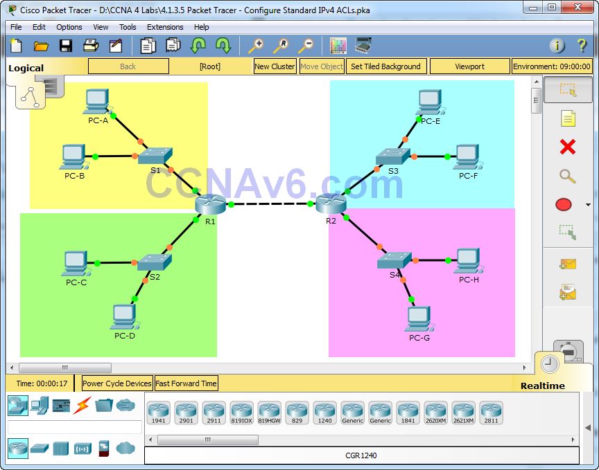
Topology
| 4.1.3.5 Packet Tracer - Configuring IPv4 and IPv6 Interfaces Instructions |
Addressing Table
Device | IPv4 Address | Default Gateway |
R1 | 172.16.20.1 | N/A |
172.16.20.129 | N/A | |
209.165.200.225 | N/A | |
NIC | 255.255.255.128 | |
PC2 | 172.16.20.138 | 172.16.20.129 |
G0/0 | N/A | |
2001:DB8:C0DE:13::1/64 | ||
S0/0/1 | N/A | |
FE80::2 | ||
PC3 | 2001:DB8:C0DE:12::A/64 | |
PC4 | 2001:DB8:C0DE:13::A/64 | |

Part 1: Configure IPv4 Addressing andVerify Connectivity
Part 2: Configure IPv6 Addressing andVerify Connectivity
Background
Routers R1 and R2 each have two LANs. Yourtask is to configure the appropriate addressing on each device and verifyconnectivity between the LANs.
Note: The user EXEC password is cisco.The privileged EXEC password is class.

Part 1:Configure IPv4 Addressing and Verify Connectivity
Step 1:Assign IPv4 addresses to R1 andLAN devices.

Referring to the Addressing Table, configure IP addressing for R1 LAN interfaces, PC1and PC2. The serial interface hasalready configured.
Step 2:Verify connectivity.
PC1 and PC2 should be ableto ping each other and the Dual StackServer.
Part 2:Configure IPv6 Addressing and Verify Connectivity
4.1 3.5 Packet Tracer Configuring Ipv4 And Ipv6 Interfaces Setup
Step 1:Assign IPv6 addresses to R2 andLAN devices.
4.1 3.5 Packet Tracer Configuring Ipv4 And Ipv6 Interfaces Configuration
Referring to the Addressing Table, configure IP addressing for R2 LAN interfaces, PC3and PC4. The serial interface isalready configured.
Step 2:Verify connectivity.
4.1 3.5 Packet Tracer Configuring Ipv4 And Ipv6 Interfaces Dhcp
1.1.3.5 Packet Tracer - Configuring Ipv4 And Ipv6 Interfaces
PC3 and PC4 should be ableto ping each other and the Dual StackServer.
